[EN] NDH 2011 badge hacking part 1 : Pinout reversing
* UPDATED (6 July 2011) *:
- Fixed links (ATMEL documentation)
- Added section on full pinout
Hello!
Today we are going to do some “hardware” hacking (if we can call it like that …). Yes, NDH badge hacking :D. I do not have any real knowledge in electronics but it should be enough to pawn it.
The thing I am the most amazed with is that nobody wrote an article about it but the creator of the badge (tixlegeek) …
Let’s fix that!
The situation
First of all, I could not not find the pinout on Tix’s Le Geek blog so I had to “reverse” it. It is because I have the following programmer (a version of USBasp):
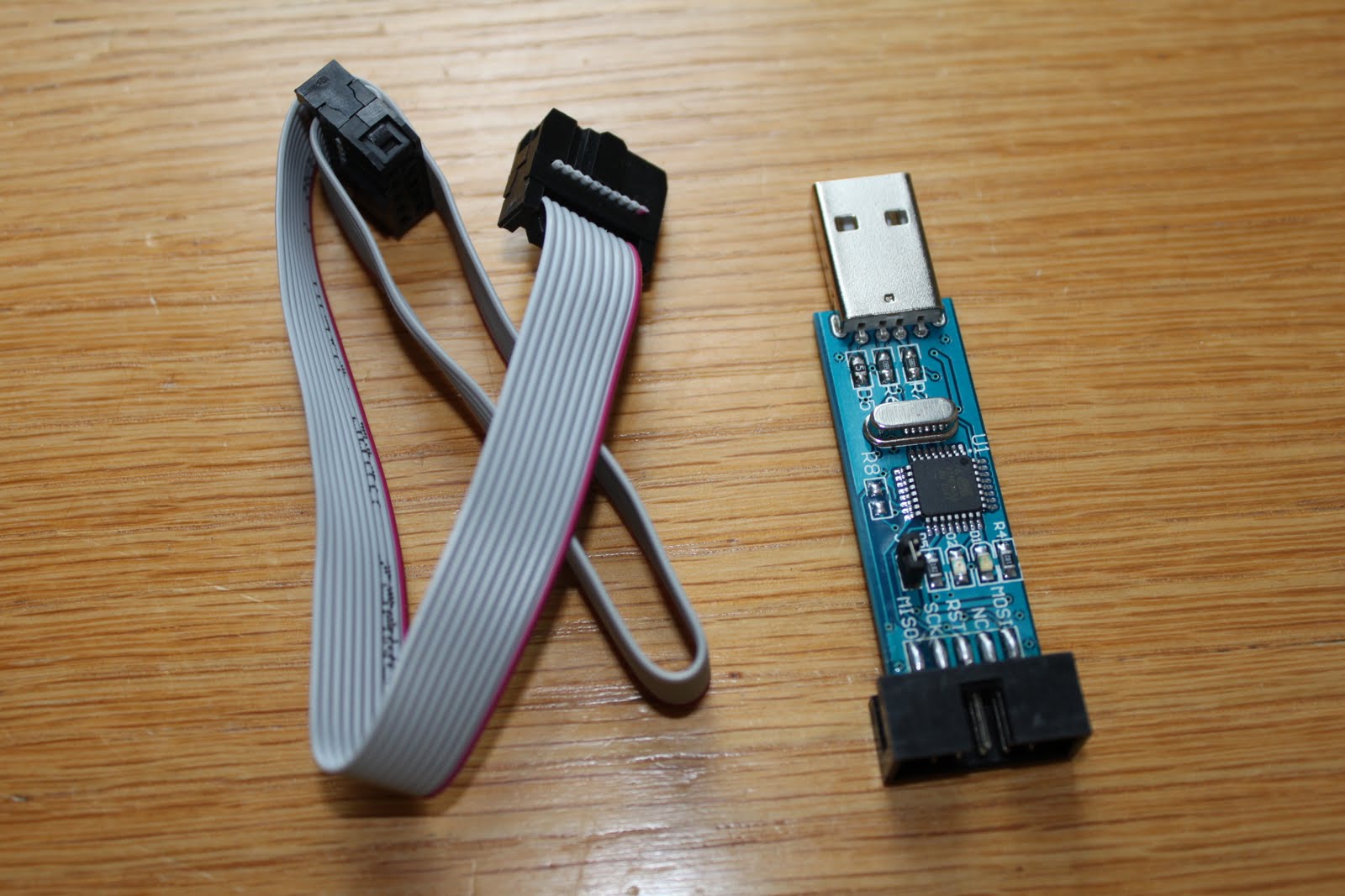
So the cable is a 2x5 pin ICSP AVR.
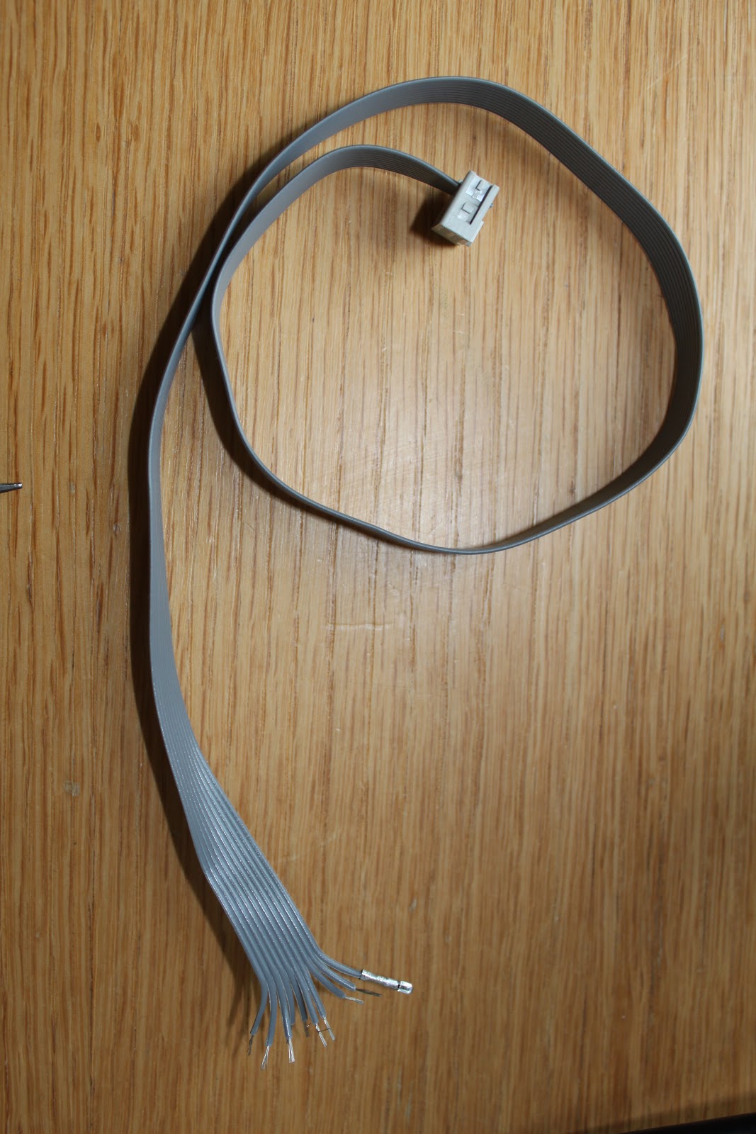
We want to have something clean so we are going to use a BUS cable:
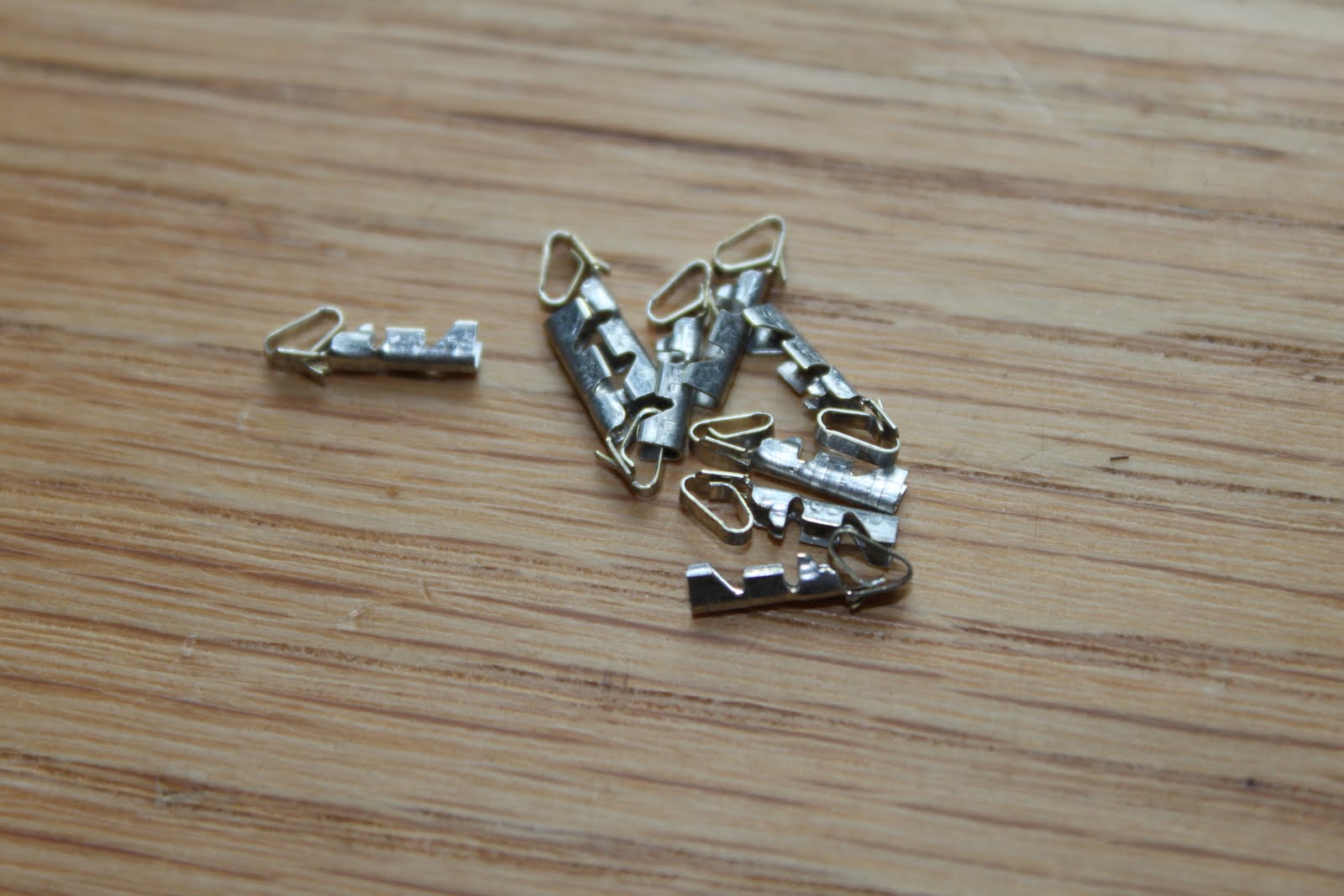
As well as small clips:
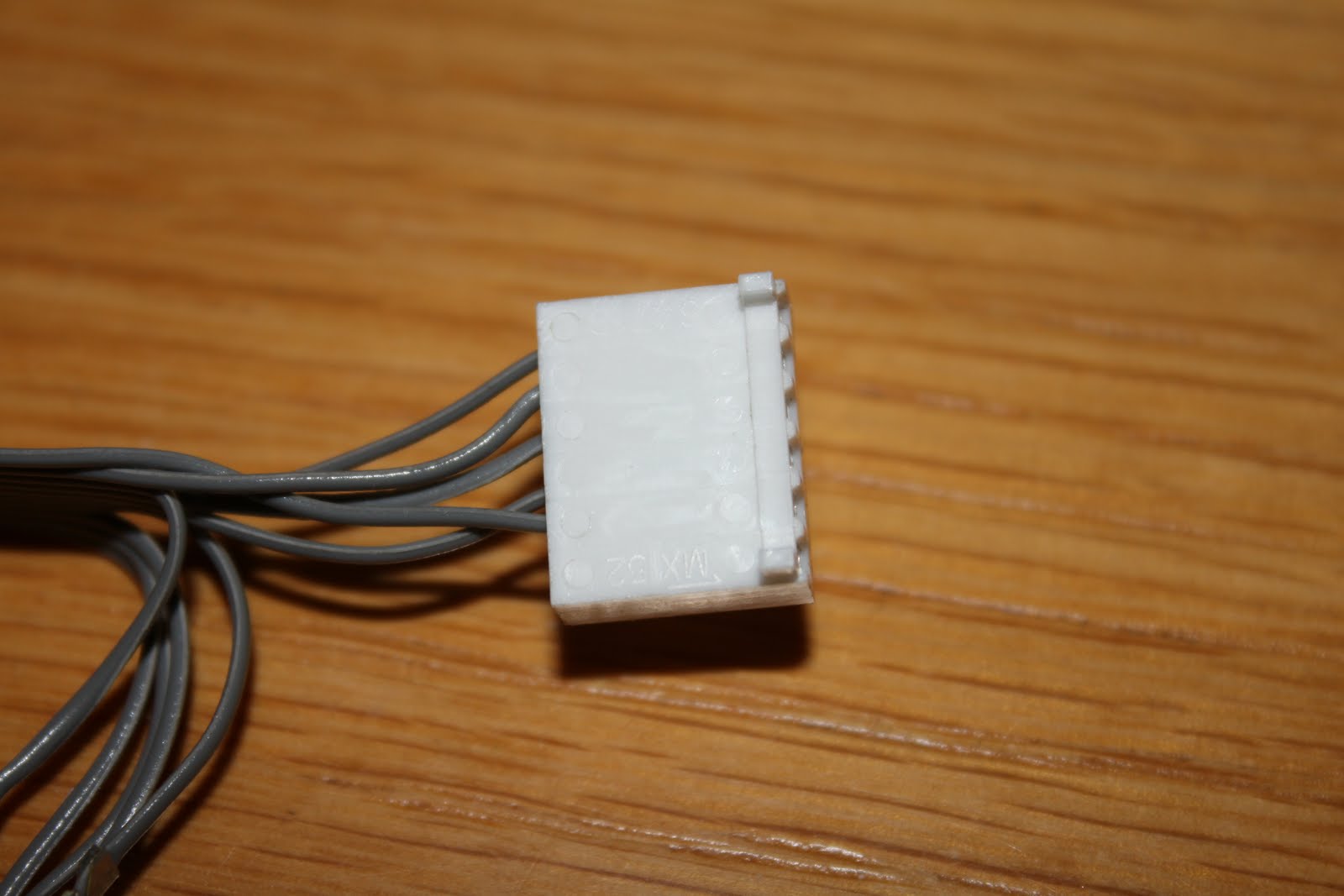
To plug it into a small socket:
To set up the clips, you need to use a flat-nosed plier like this:
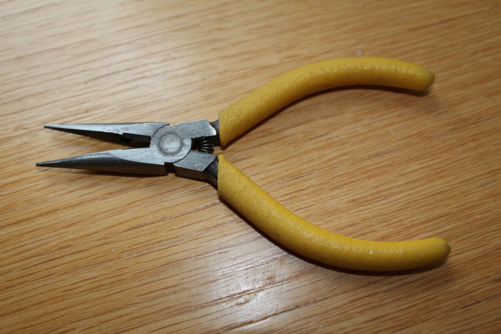
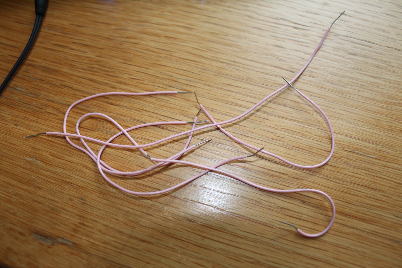
For reversing the pinout you could also use wires and a breadboard (I don’t have a breadboard … or any electronic stuffs ^^”):
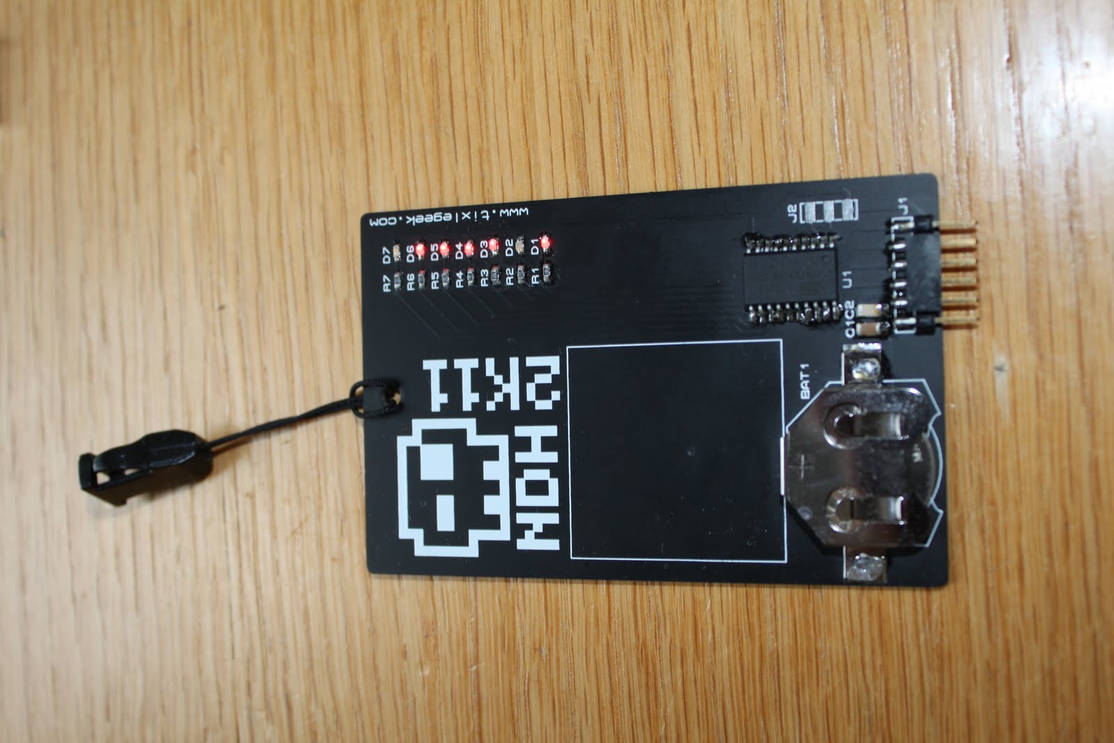
Don’t forget your NDH badge!
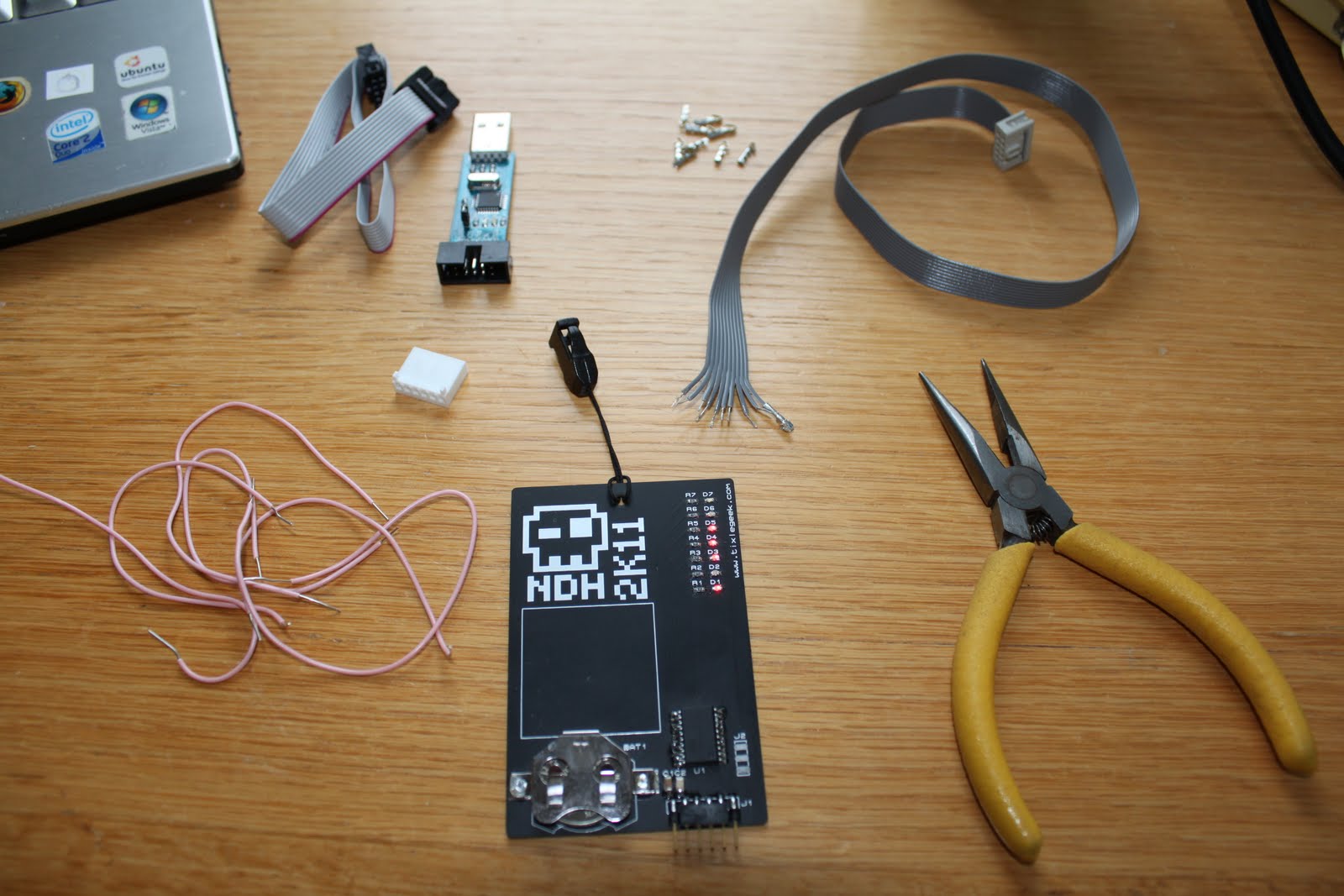
In the end you should have all those:
Reversing the pinout
Ok for the pinout you could try to find VCC and GND first with a multimeter and then the other ports. As I do not have any electronic equipment I haven’t tried that.
But here what was my idea with the wires :
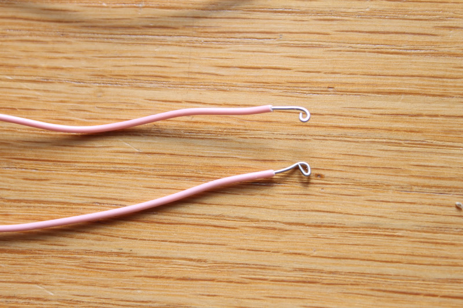
Yeah, try to craft kind of a hook or something and plug the other part to a breadboard and test it.
Luckily there is another way to find out about the pinout:
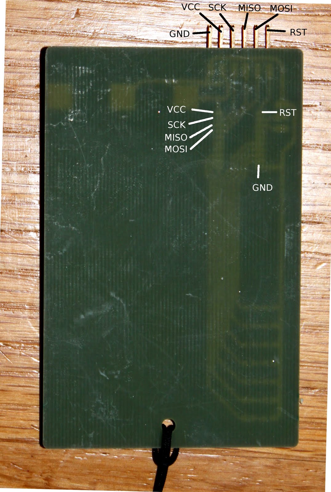
Yes just looking at the chip documentation you could find the pinout. Anyway for the chip, looking close enough you could see its reference:
1
2
ATMEL 1114
ATTINY2313V-10SU
Done we have the pinout. Just have to make the cable ;).
The pinout
Badge NDH
1
2
3
-------------------------------------------------
    |       |       |       |       |       |
   RST    MOSI    MISO     SCK     VCC      GND
Port 2x5 ping AVR ICSP
1
2
3
4
5
6
7
    1           3         5           7          9
---------------------------------------------------------
|   MOSI    |   NC  |   RESET   |   SCK     |   MISO    |
---------------------------------------------------------
|   VCC     |   GND |   GND     |   GND     |   GND     |
---------------------------------------------------------
    2           4         6           8          10
Do the pinout and then we’re in business :).
Full pinout
Just in case people might find this useful:
1
2
3
4
5
6
7
8
9
10
11
12
13
14
15
16
17
18
19
20
21
22
23
24
25
26
27
28
-------------------------
|          PORTD        |
-------------------------
|   PIND0   |   RX      |
|   PIND1   |   TX      |
|   PIND2   |   D4      |
|   PIND3   |   D3      |
|   PIND4   |   D2      |
|   PIND5   |   D1      |
|   PIND6   |   D5      |
-------------------------
|          PORTB        |
-------------------------
|   PINB0   |   D6      |
|   PINB1   |   D7      |
|   PINB2   |   NC      |
|   PINB3   |   NC      |
|   PINB4   |   NC      |
|   PINB5   |   MOSI    |
|   PINB6   |   MISO    |
|   PINB7   |   SCK     |
-------------------------
|          PORTA        |
-------------------------
|   PINA0   |   NC      |
|   PINA1   |   NC      |
|   PINA2   |   RESET   |
-------------------------
It is evident that you need to read the documentation to understand that table: the chip documentation.
Conclusion
With a bit of curiosity, it was possible to find out about the pinout fairly easily. As I miscounted the AVR ICSP pinout … my cable is not right, so the software part is going to be for another day ;).
Cheers,
m_101